The part number often arrives before the joint does. The rivet is picked first, and the sheet is adjusted until it fits: the hole opened up, a flange trimmed, a gap widened for the tool. The part is then a constraint on the joint.
The rivet is where the specification ends, not where it starts.
That does not mean the rivet is ignored until the end. It means the final part specification should follow the interfaces it has to satisfy.
Questions about how to specify blind rivets come back to the same ground: when each decision has to be made, what it locks in place, and what has to be confirmed before the order goes out.
What Do You Need Before You Can Specify a Blind Rivet?
You are ready to specify when the joint envelope, the interfaces and the exposure have stopped moving. The specification is still open when any of the three is still a preference.
Those three are what the part choice is measured against. Until they settle, every candidate is compared against a moving target.
“Stopped moving” does not mean the entire product is frozen. It means the decisions that define the rivet interface are stable enough to release and verify.
The goal is stability, not absolute certainty: an agreed joint envelope can be documented and checked while details are still approximate.
The common error is small enough to miss: the part number is picked first, and the joint is made to fit it. The rivet becomes a limit on the sheet instead of a consequence of it.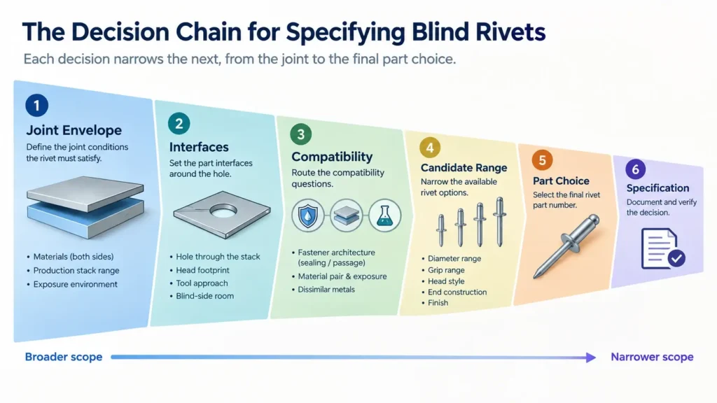
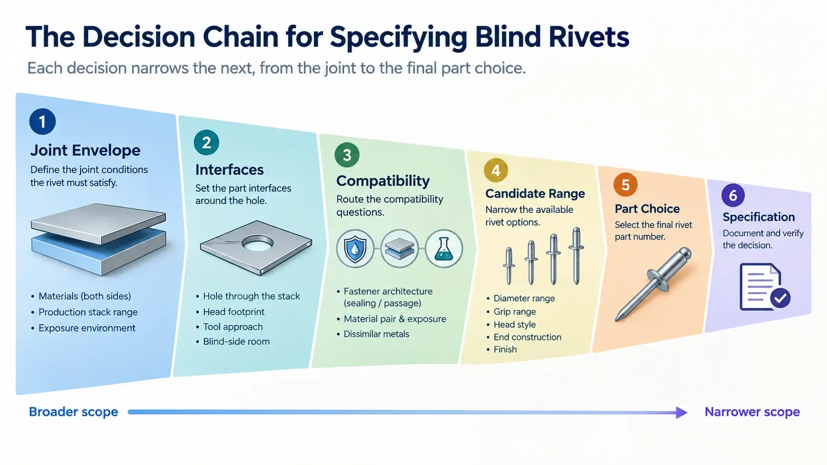
The order is not a formality; each decision narrows the next.
What Does the Joint Have to Do Before Any Rivet Is Chosen?
The joint is what the rivet has to satisfy, so it is described before the rivet is considered.
What meets at the joint. The sheets, the fastener materials, and any coatings or other surfaces that come into contact. Few joints are a single material pair, and not all are visible from the outside.
The stack the line will build. Not the thickness on the drawing, but the thickness the process produces. Burrs, forming springback, coatings and sheet thickness variation all add to it, and not the same way on a prototype as on a production run. The description should state which side is measured, who measures it, and how the measurements are taken; otherwise, the range remains a drawing value.
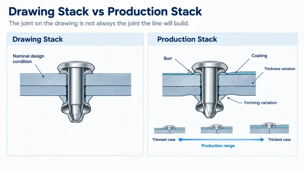
What the joint is exposed to. Dry or wet, washed down or sheltered, dusty or clean, and whether both faces stay visible.
How much the joint has to carry is one of its limits. Where that capacity has to be turned into a number, our guide to blind rivet shear vs tensile strength covers the values and what they mean.
The same part often changes thickness along the joint — a hem, a bracket, a reinforcement plate. Where it does, the description covers the thinnest to the thickest the line will build, or the joint is split into zones.
Which Decisions Are Expensive to Reverse?
Decisions are not ranked by importance; they are ranked by how expensive they are to undo.
Most sit at one of three levels: a change on the part itself — sheet metal or a die — lands on parts that already exist; a change at the tool level means another tool or fixture; at the part-number level, a different rivet.
The part choice is often easier to revisit than a frozen product interface.
The sequence is a decision order, not a one-way engineering process. Earlier decisions can be revisited; the point is to avoid locking the part choice before the interfaces it has to satisfy are stable.
The table below sets out what fixes each decision and what changing it costs later.
Table 1 — What Each Decision Locks
| Decision area | What fixes it | Still open until | What changing it costs after that |
|---|---|---|---|
| The joint envelope | The parts and the process | The first parts are prototyped | A change on the joined parts |
| The hole through the stack | The sheet drawing and process | The first parts are made | Rework or new tooling |
| The head footprint | The layout around the hole | The layout is frozen | A change around the hole |
| The setting tool approach | Tool choice and shop layout | The tool is ordered | A different tool or fixture |
| The compatibility route | The joint exposure and material pair | The compatibility constraints are defined | A different part architecture or material |
| The rivet part choice | The joint envelope and the interfaces | Candidate options are compared | A different part number |
The sequence follows the cost of changing your mind.
Which Constraints Come From the Product, Not the Rivet?
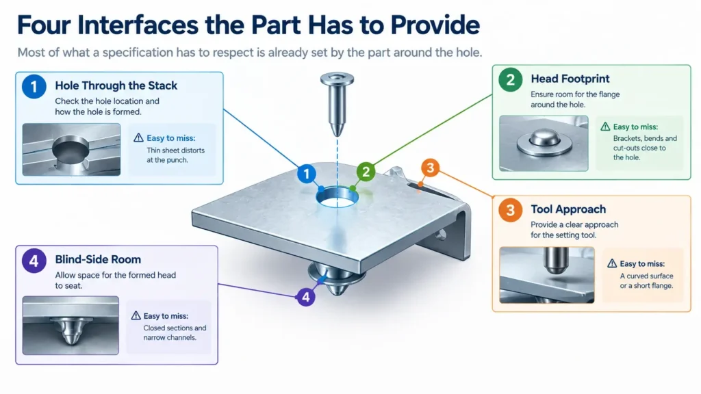
Most of what a specification has to respect is already set by the part around the hole.
Four interfaces on the part decide what the rivet is allowed to be, and each has a place where it is easy to miss — thin sheet at the hole, brackets and cut-outs at the flange.
The blind side is the interface most often left to the shop floor: enough room has to exist for the fastener to form and seat, and the final installed geometry differs from the fastener’s geometry before setting. Confirm it while the part can still change.
Table 2 — Interfaces the Part Has to Provide
| Interface | What has to be checked on the part | Where it is easy to miss | Settled by |
|---|---|---|---|
| Hole through the stack | The hole location and how the hole is formed | Thin sheet distorts at the punch | Sheet drawing and process |
| Head footprint | Room for the flange around the hole | Brackets, bends and cut-outs close to the hole | Sheet layout |
| Tool approach | Clear access for the setting tool | A curved surface or a short flange | Tool choice and fixture |
| Blind-side room | Space for the formed head to seat | Closed sections and narrow channels | Joint and part design |
The interfaces above sit outside the rivet. What the rivet itself provides is a separate set of values.
The stack the line will build is part of the joint envelope, not an interface.
The fit at the hole itself is a separate decision with its own limits; blind rivet hole size covers them.
Where Do the Compatibility Questions Belong in the Sequence?
Compatibility is a routing step, not a selection lesson. Each question below has a different owner, and naming it is the point.
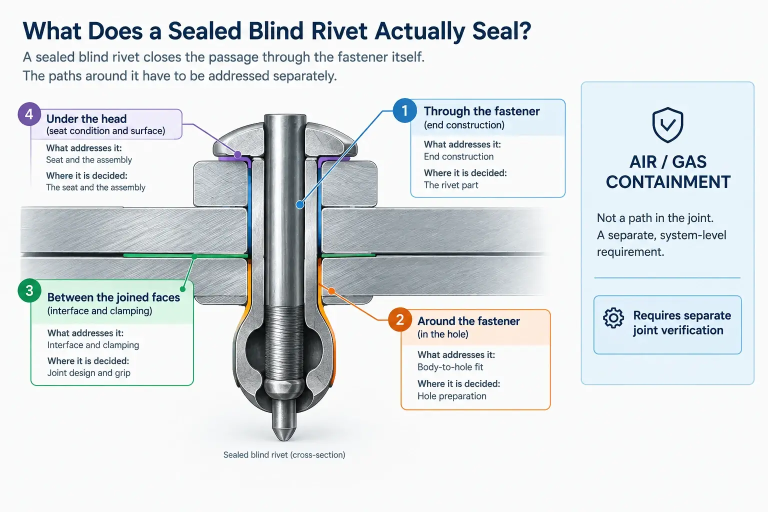
- Does the joint require a fastener architecture that limits passage through the fastener itself? That belongs to joint architecture and sealing.
- Does the joint stay in contact with an electrolyte or with contaminants? That belongs to the material pair and the exposure.
- Are dissimilar metals joined? That belongs to material compatibility.
Compatibility questions are decided against the joint; they cannot be settled by looking at a part number.
Only after these questions have an owner should the rivet part be narrowed down.
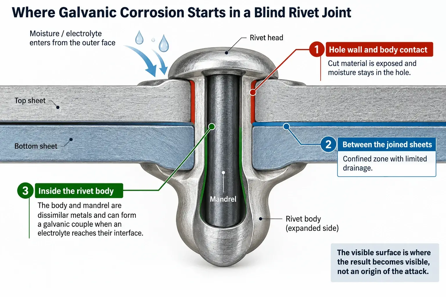
Where dissimilar metals and wet exposure are both present, the compatibility question deserves separate review: blind rivets and galvanic corrosion.
What Can Only Be Confirmed on a Real Sample?
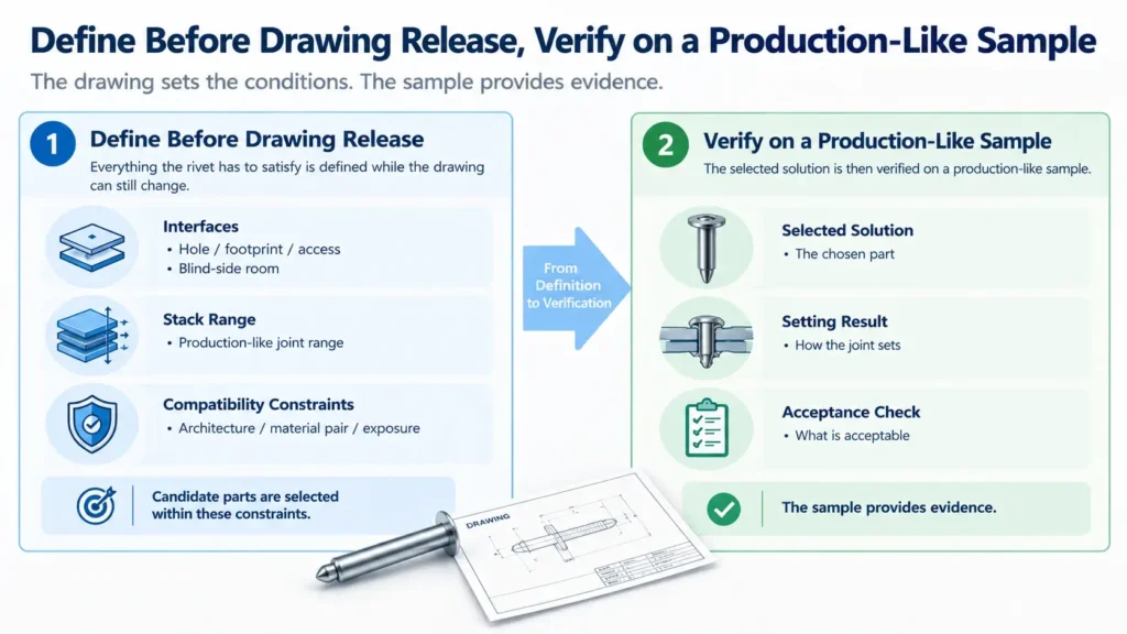
Define Before Drawing Release. Everything the rivet has to satisfy is defined while the drawing can still change: the four interfaces, the production stack range, and the compatibility constraints from routing. Candidate parts are selected within those constraints; the selected solution is then verified on a production-like sample.
What has to be frozen before the drawing is released is frozen for a reason, not for caution.
The drawing defines the conditions the rivet must satisfy. The sample provides evidence that the selected rivet satisfies them.
The sample has to be built the way the line will build it, or it measures something else. It should also represent the defined stack range.
Verify on Production-Like Sample. The selected part is then run across that range: whether it sets and holds as expected, whether the end construction and finish behave as intended here, and what the setting result looks like.
What is checked on the sample is what can be seen on it: a head formed completely, a head seated against the sheet, joined parts not crushed or deformed, and a formed head with somewhere to sit.
When the first parts do not set cleanly, the cause is usually traced through the tool, the hole and the rivet in that order; blind rivet setting problems works through it.
What Goes on the Specification You Send?
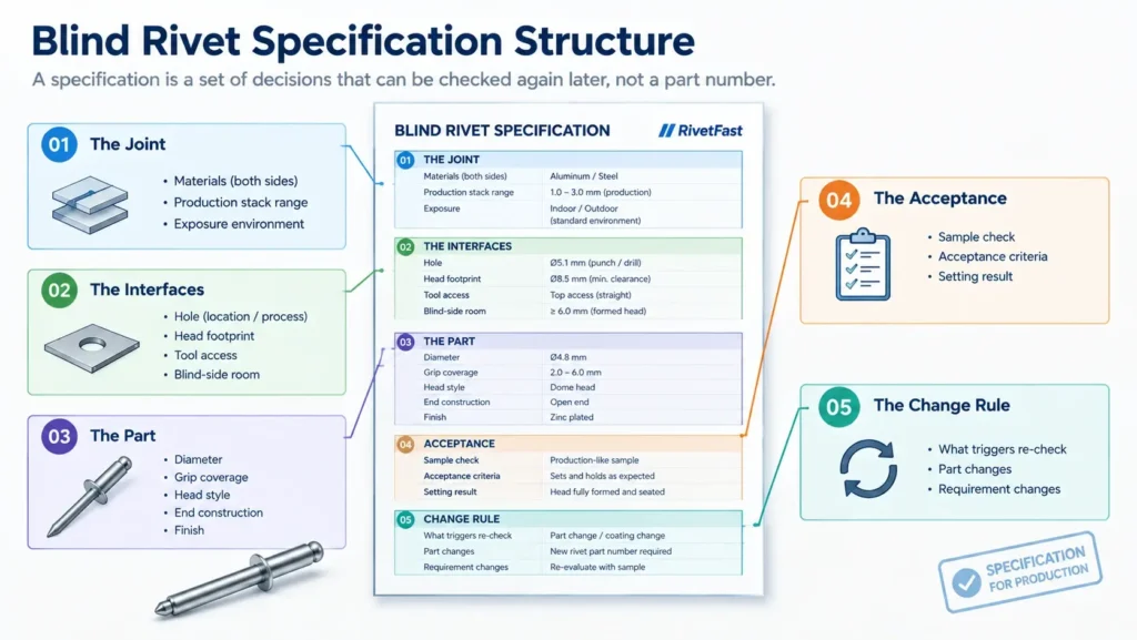
A specification is a set of decisions that can be checked again later, not a part number.
Five groups go into it: the joint, the interfaces, the part, the acceptance, and the change rule. Each answers a question that will come back.
The part group is the shortest of the five — the selected part characteristics, matched to the joint. The rest makes them checkable.
Table 3 — What the Specification Carries
| Field group | What it states | Where the value comes from |
|---|---|---|
| The joint | Materials, the real stack range, the exposure | The part drawing and the process |
| The interfaces | The hole the joint is made to, footprint, access | The sheet drawing |
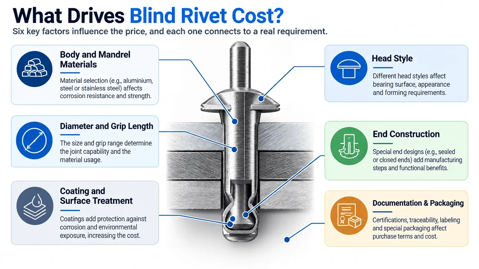
| The part | Diameter, grip coverage, head style, end construction, finish | The joint constraints, applied to the available options |
| The acceptance | What is checked on the sample, and what counts as acceptable | Defined by the project team before sample review |
| The change rule | What triggers a re-check of the specification | The specification itself |
If the part changes behind the same part number, the specification has to be re-checked, not just re-ordered.
A different coating or mandrel can leave the part number unchanged while changing the part; the specification should then be re-checked against the joint.
One habit is worth keeping: state what is still open, on purpose. Otherwise, an empty field is taken as finalized.
Specifying blind rivets for a new product ends with a record the project can check.
What arrives from a supplier is a set of values to compare against this specification; how to read a blind rivet datasheet covers those fields.
FAQ
1. What information should be ready before you request a quote?
The joint description first: the materials on both sides, the stack range the line will build, what it has to carry, and the exposure. Then the interfaces: the hole, the room around it, the tool access.
2. Should the hole size be fixed before the rivet is chosen?
The hole is a product interface, so it should be defined from the joint and part design rather than selected around a rivet part number.
3. What if the stack thickness varies across the same part?
Then the description covers the range, or the joint is split into zones. The part has to suit each range the description defines, burrs and coatings included.
4. What belongs on a rivet specification?
Five groups: the joint, the interfaces, the part, the acceptance, and the change rule. The part group is the shortest; the rest makes that choice checkable later, including what is deliberately still open.
5. Can a specification be released before a sample is set and checked?
There are two checkpoints. The interfaces and design constraints can be released once they are defined and stable; the selected part still needs production-like sample verification before it is treated as verified.
6. What happens when a supplier changes the part behind the part number?
The number stays the same, so the change does not show up in the order. A supplier change can alter how the part behaves here; if it touches a defined requirement, the specification has to be re-checked.
Start With the Joint, Keep the Part for Last
Define the joint → fix the interfaces → route the compatibility questions → choose the part → verify on a sample → then release.
Most of what a rivet has to satisfy comes from the joint around it. Describing that joint early is what makes the later choices small, and what makes them checkable at the end.
The joint sets the limits. The sequence keeps them reachable.
Send us your application, the joint materials and the stack range the line will build, the expected quantity, and the service environment. We can review the joint interfaces, narrow the candidate range, and support sample verification before production.